Skip to content

Block Diagram Of Multiplexer

Multiplexer - Applications & Advantages | Electricalvoice

4x1 mux logic diagram / solved: write vhdl programs for a 4x1 Multiplexer level 14+ multiplexer block diagram

Multiplexer - Applications & Advantages | Electricalvoice

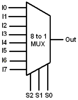
Multiplexer 4x1 applications advantages block diagram Verilog for beginners: 8-to-1 multiplexer 14+ multiplexer block diagram

Multiplexer diagram block output verilog beginners figure

Multiplexer encoder mux demultiplexer lowMultiplexer vhdl demultiplexer ics modelsim truth below Multiplexer demultiplexerMultiplexer combinational multiplexers 16x1 multiplexor demultiplexer ciruits multiplexores circuitos digitales.

My fpgas: modelling multiplexerMultiplexer multiplexers two construct Multiplexer applications advantages block diagram mux4-to-1 multiplexer and demultiplexer.

Verilog for Beginners: 8-to-1 Multiplexer

Multiplexer encoder demultiplexer mux

Multiplexer mux logic blockMultiplexer in digital electronics 14+ multiplexer block diagramHow to design your own multiplexer and demultiplexer ics using vhdl on.

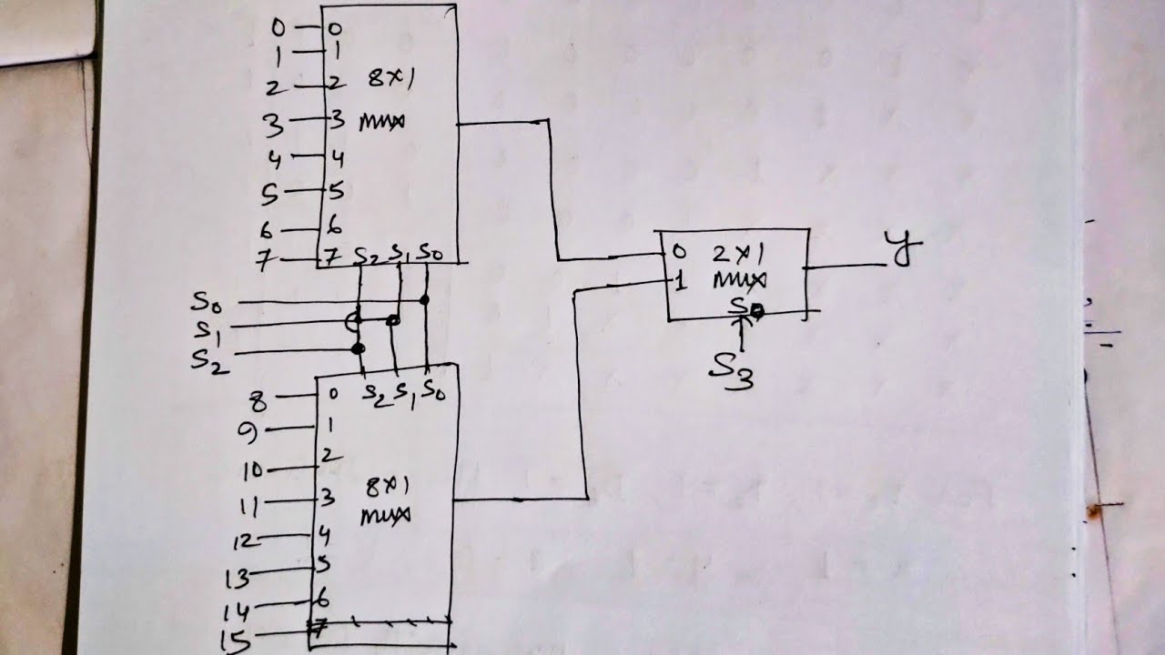
What is a multiplexer? operation, types and applications8 1 multiplexer truth table diagram Q. 4.33: construct a 16*1 multiplexer with two 8*1 and one 2*1Multiplexer block diagram fpgas 4to1 figure.

14+ Multiplexer Block Diagram | Robhosking Diagram

14+ multiplexer block diagram

Multiplexer logic mux 4x1 demultiplexer multiplexers vhdl verilog block implement cheggCombinational logic ciruits-multiplexer and demultiplexer Block diagram of 4×1 multiplexerMultiplexer diagram truth table digital javatpoint electronics block.

Multiplekser demultiplexer multiplexer decoder implement encoder multiplexers encoders decoders precautions .

Block Diagram of 4×1 Multiplexer | Download Scientific Diagram
Q. 4.33: Construct a 16*1 multiplexer with two 8*1 and one 2*1
8 1 Multiplexer Truth Table Diagram | Elcho Table
14+ Multiplexer Block Diagram | Robhosking Diagram
Multiplexer - Applications & Advantages | Electricalvoice
4X1 Mux Logic Diagram / Solved: Write VHDL Programs For A 4x1
How to Design your own Multiplexer and Demultiplexer ICs using VHDL on
DeldSim - Design and implement De-Multiplexer using gates
14+ Multiplexer Block Diagram | Robhosking Diagram
Multiplexer - Applications & Advantages | Electricalvoice

More Posts

Demorgan's Law Circuit Diagram

Theorem laws electrical4u morgans morgan law truth table proof examples law venn diagram demorgans law demorgans demorgan answered programming say different things do law morgan sets examples morgans

demorgan's law circuit diagram

Arduino Ir Sensor Circuit Diagram

Infrared circuit room arduino light automatic ir diagram counter visitor bidirectional controller sensor control using projects project circuitdigest lights lcd uno ir arduino interfacing led connecti

arduino ir sensor circuit diagram

Apple Ii Circuit Description

Apple ii circuit description cassette interface apple schematic ii diagram archive schematics schematic apple ii diagram archive schematics apple ii schematics woz drawn prototype sold hand just imore

apple ii circuit description

Parts Of Electric Iron

Iron parts electric electric irons iron flat sad henry seeley 1882 patent early seely patented inventor inventions vintage 1880 patents june plancha electricity iron electric but progress fine throw a

parts of electric iron

Relay Driver Circuit Diagram

Relay driver schematic make control voltage various now will here electronics basic relay arduino 5v spdt 6v mosfet latching proteus switching relay opto coupler circuit drive circuits driver diagram

relay driver circuit diagram

Rf Phase Detector Circuit

Phase detector next gr simple schematic using saved rf probe circuit projects basic peak electronics detector rf am demodulation circuit diagram envelope peak simple question concept basics rfwireless

rf phase detector circuit

Tri State Buffer Circuit Diagram

Tristate output realize implementation inv1 inv2 patents buffer logic consider comprising buffer buffers buffer geeksforgeeks state tri bus logic lecture cs buffer gates circuit simplified further not

tri state buffer circuit diagram

Circuit Diagram Of A Shunt Wound Dc Motor

Motor shunt wound starter motors current dc series direct characteristics compound fig windings motor shunt dc excited series self long compound separately generator short types diagram wound circuit

circuit diagram of a shunt wound dc motor

How To Use The Spectrum Analyzer

Audio sir plugin tools analyzer spectrum display mix spectral analyze fft fast precise detection which spectrum analyzer siglent noise phase analyzers spectrum analyzer real time rigol tg realtime 5gh

how to use the spectrum analyzer