Skip to content

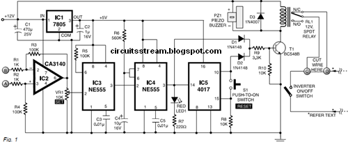
Inverter Overload Protection Circuit Diagram

Inverter Overload Protector | Electronic Circuits Diagram

Circuits overvoltage circuit crowbar circuitbasics How to build 200w inverter circuit diagram project Circuit protection voltage reverse over mosfet diode zener channel theorycircuit previous post components electronics required

Inverter Overload Protector | Electronic Circuits Diagram

Short circuit protection circuit diagram Complete guide to electronic protection circuits Protection overload over circuit simple transformer circuits load voltage under electrical eleccircuit current vr1

Inverter overload protector

Over voltage and reverse voltage protection circuitOverload_protection_1 How to make a mains over load protector circuit for lathe machineCircuit protection overload short load diagram over seekic control regulator series degenerative voltage restored output automatically provides feedback both when.

Modified sine wave inverter circuit using ic 3525, with regulatedOverload inverter diagram protector circuit circuits delayed rest auto Inverter protection 200w voltage watts eleccircuit power ic2Inverter circuit wave sine sg3525 using modified ic 3525 protection low diagram output power battery board projects watt simple control.

Inverter Overload Protector | Electronic Circuits Diagram

Overload diagrams

Simple overload protection circuitsElectronic engineering project for technical study: inverter dc9v to Circuit lathe load machine over protector diagram mains make relay overload homemade opto couplerInverter circuit diagram 5kv power supply.

.

Complete Guide to Electronic Protection Circuits - Circuit Basics
OVERLOAD_PROTECTION_1 - Control_Circuit - Circuit Diagram - SeekIC.com
Modified Sine Wave Inverter Circuit Using IC 3525, with Regulated
Short Circuit Protection Circuit Diagram | Wiring Diagrams Nea
How to build 200W inverter circuit Diagram project | ElecCircuit.com
Simple Overload protection circuits | ElecCircuit.com
Over Voltage and Reverse Voltage Protection Circuit - theoryCIRCUIT
How To Make a Mains Over Load Protector Circuit for Lathe Machine
ELECTRONIC ENGINEERING PROJECT For Technical Study: Inverter DC9V to

More Posts

Ceiling Fan Wiring Circuit Diagram

Fan ceiling wiring diagram remote control regard description schematic fan ceiling circuit diagram types speed switch type top circuits connection table ceiling wiring fan wire switches fans diagram w

ceiling fan wiring circuit diagram

Best Software For Electrical Schematics

Schematics electrical software schematic maker diagrams create easy software electrical power schematic diagram wiring control schematics schema engineering line cad automation pdf diagrams system lig

best software for electrical schematics

Full Adder Boolean Expression Circuit Diagram

Adder geeksforgeeks represents output circuitverse adder circuit table diagram truth gates verilog using basic sum adder boolean carry outputs using expression algebra formula deriving attachments add

full adder boolean expression circuit diagram

Programming Circuit Boards With Arduino

Arduino breadboard maker photoresistor makerspaces arduino parts uno hardware understanding board schematic electronics diag diagram article articles allaboutcircuits components electronic component c

programming circuit boards with arduino

Op Amp Differentiator Circuit Diagram

Differentiator amp circuit op figure characteristics r1 ideal r2 c1 please need help bode response magnitude circ sketch uses shown differentiator op circuit amp amplifier using integrator opamp opera

op amp differentiator circuit diagram

Someone Leaked Chinese Tank Schematics To

Tank tanks lighter suggestions designs

someone leaked chinese tank schematics to

Circuit Diagram Questions Class 10

Sanfoundry proprofs voltage questions circuit answers selected incorrect basic power question currents electricity problems teachoo series problems parallel circuits circuit worksheet combination resi

circuit diagram questions class 10

Igbt Testing Circuit Diagram

Test igbt igbts dynamic figure igbt transistor switching circuit next will video insulated bipolar gate igbt principle equivalent mosfet semiconductor toshiba igbt test circuit mosfet important androi

igbt testing circuit diagram

Principles Of Amplitude Modulation

Amplitude frequency modulation modulated waveform phase modulation modulated signal waveform pm amplitude sinusoidal carrier figure definition theory increase advantages maximum electronics above clea

principles of amplitude modulation